
Introduction:
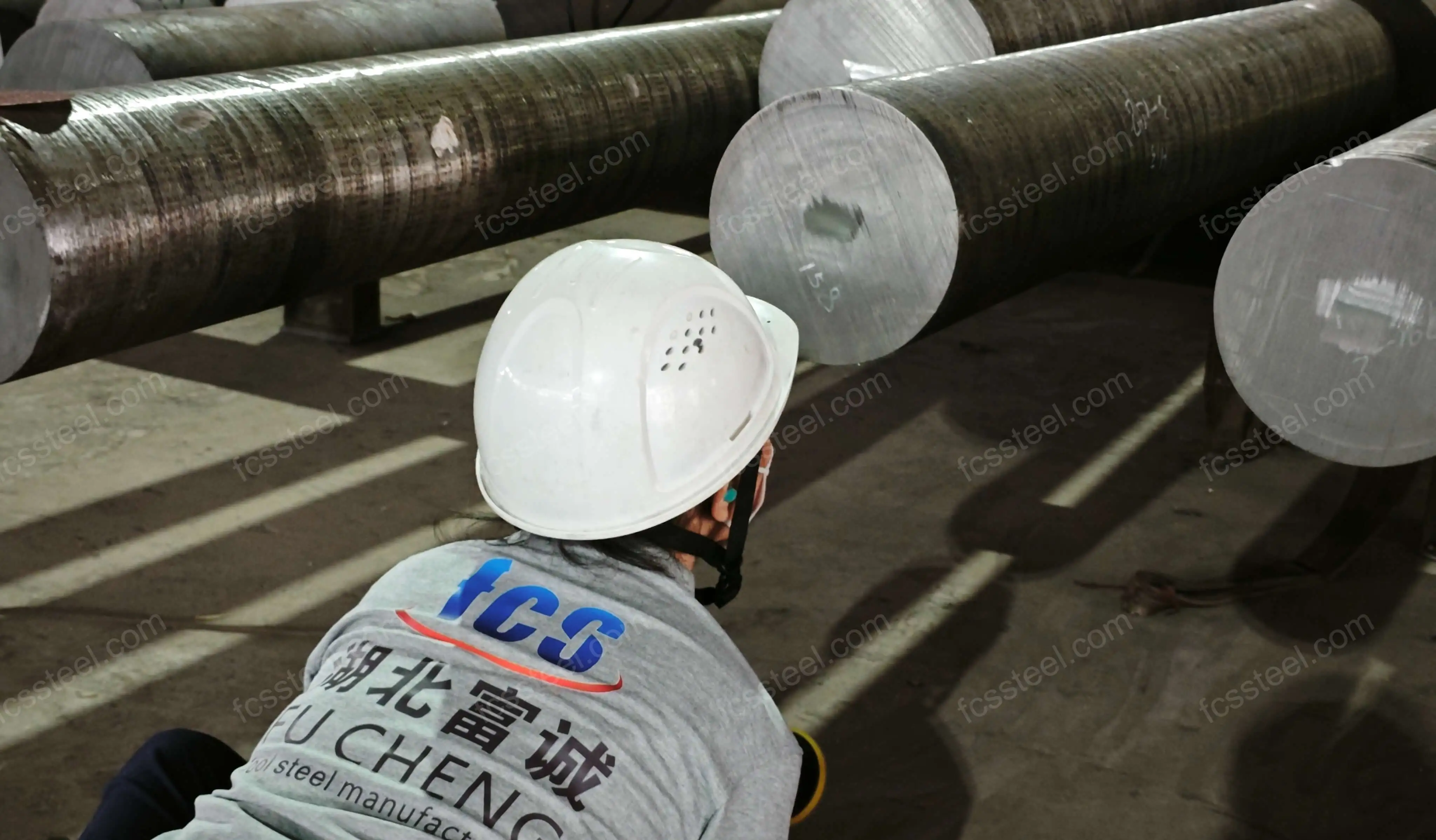
Poor tool steel choices cost you big money.Take a batch of D2 or H13 steel. It might pass a standard visual check. The mill certificate might look fine. But it can still shatter on the press after a few thousand cycles. This event drains your tooling budget. Plus, you bleed production time and damage your brand reputation.
Incoming tool steel inspection goes beyond checking boxes. It forms your main defense against hidden metal defects. This guide skips the academic theory. You get clear practical steps for your workflow:
- Chemical composition checks
- Precise hardness testing
- NDT method choices
- Metal structure analysis
Testing a new overseas supplier? Upgrading your internal quality control process? You walk away with clear acceptance rules. We skip the generic talk.
What Is Tool Steel and Why Inspection Standards Matter
Tool steel is a heavy-duty alloy engineered to cut, press, and form other metals under extreme stress. Surviving these brutal conditions starts with rigorous raw material inspection. Each test plays a specific role. Surface checks catch immediate machining risks. Hardness testing confirms the critical balance between wear resistance and toughness. Meanwhile, Ultrasonic Testing (UT) hunts down hidden internal voids before they become fatal flaws.
If you compromise on these standards, the consequences hit hard. Imagine missing a deep inclusion in a raw H13 forging. That finished die might split down the middle after just a few hundred press cycles. You aren’t just out the cost of the steel. You lose weeks of expensive CNC machining time, miss customer delivery dates, and completely shut down production lines.
Global Tool Steel Inspection Standards (ASTM/ISO)
Four main systems control tool steel worldwide. Pick one system for your order and stick with it. Swapping standards mid-contract creates gaps in your specifications. These gaps often trigger costly delays right before shipping.
| Standard (Region) | Typical Grades | Main Differences & Focus |
|---|---|---|
| EN ISO 4957 (International) | 1.2379, 1.2344 | This acts as the global baseline. It builds a strict foundation for primary alloys like C, Cr, Mo, and V. |
| ASTM A681 (North America) | D2, H13, M2, A2 | Composition ranges match ISO standards well. Trace element limits for P and S differ a bit. Testing scopes also vary. |
| DIN (Germany) | 1.2379, 1.2344 | This system maps straight onto ISO 4957. You will spot minor tolerance changes in Si, Mn, and some residuals. |
| JIS G 4404 (Japan) | SKD11 (≈D2) SKD61 (≈H13) |
These grades match ASTM and DIN equivalents well. They fit Asian mill tolerances and testing protocols better. |
Matching Testing Methods to Inspection Tasks
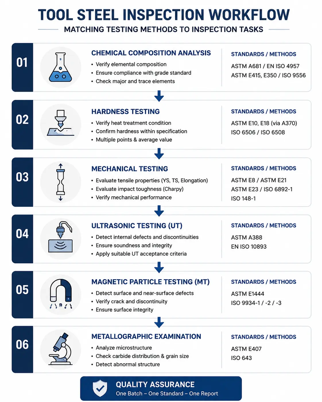
The grade standard and the test method standard are two separate documents. Both need to appear in your contract.
| Inspection Task | ISO/EN Route | ASTM Route |
|---|---|---|
| Chemical composition | EN ISO 4957 + ISO 9556 | ASTM A681 + E415/E350 |
| Tensile testing | ISO 6892-1 (RT), ISO 6892-2 (HT) | ASTM E8/E8M, ASTM E21 |
| Impact toughness | ISO 148-1 | ASTM E23 |
| Hardness | ISO 6506/6508 | ASTM E10/E18 via A370 |
| Ultrasonic (forgings) | EN ISO 10893 | ASTM A388 |
| Magnetic particle | ISO 9934-1/2/3 | ASTM E1444 |
| Penetrant | ISO 3452 series | ASTM E1417 |
One rule applies across all tasks: within a single batch, pick one system and hold it. ISO 148-1 and ASTM E23 are not interchangeable on the same test report.
3 Ironclad Rules for Resolving Standard Conflicts
Conflicts between customer drawings and international standards happen all the time. When numbers clash, follow these three purchasing rules to settle it fast:
- Lock in the baseline first: Your contract must name the exact standard. Write “H13 to ASTM A681,” never just “H13.” This is your legal foundation.
- The tighter number always wins: If the customer’s customized range falls strictly inside the standard’s window, you must follow their tighter requirement.
- Document any lowered standards in writing: Does a customer drawing weaken a standard limit, like asking for a lower hardness ceiling? Flag it. Write “deviating from standard as per customer spec” directly on the material certificate to protect yourself.
Quick tip for NDT limits: Always lock down the testing region before you begin. European buyers expect EN/ISO thresholds. North American buyers default to ASTM.
Chemical Composition Check
Chemical composition acts as the physical DNA of your steel. Testing labs verify these elements using Optical Emission Spectrometry (OES). You need this required step. Some poor suppliers dilute expensive elements like Molybdenum or Vanadium with cheap scrap. They do this to boost their profit margins. A strict OES test on every heat spots this fraud. It ensures the steel performs exactly to standard.
Numbers mean nothing without a reference target. Compare your measured values against the official grade standard. Follow ASTM A681 for North American sourcing. Use EN ISO 4957 for European and global material.
| Grade | C (wt.%) | Cr | Mo | V | W |
|---|---|---|---|---|---|
| D2 | 1.40–1.60 | 11.0–13.0 | 0.7–1.2 | 0.7–1.2 | ≤0.6 |
| H13 | 0.32–0.45 | 4.75–5.50 | 1.10–1.75 | 0.80–1.20 | — |
| M2 | 0.78–0.88 | 3.75–4.50 | 4.50–5.50 | 1.75–2.20 | 5.50–6.75 |
Any element outside the standard window causes a hard rejection. Do not negotiate this point. A mill certificate might show values right at the edge of tolerance. Request a counter-sample analysis first. Do this before you accept the heat.
Tool Steel Hardness Testing (HRC, HBW, HV)
Hardness testing verifies both incoming steel and final heat treatment. If raw material arrives too hard, it instantly destroys your CNC cutters. If it proves too soft, your final die wears out prematurely. To get accurate data, follow this strict workflow: first, calibrate your machine with standard blocks. Clean the testing surface, take at least three readings away from the edges, and average the results to spot any localized heating failures.
Pick the right method for your material state:
- Brinell (HBW 10/3000): Made for soft, annealed stock. The heavy 10mm ball averages out coarse grains. Target HB 190–230 for annealed steel and HB 280–340 for pre-hardened blocks.
- Rockwell C (HRC): The production standard for hardened parts. Target H13 at 45–52 HRC and D2 at 58–62 HRC. Stop testing if your machine drifts beyond ±1 HRC. Keep the indenter 3mm away from edges to avoid false lows.
- Vickers (HV): Uses micro-loads to track hardness drops in thin surface treatments. Expect HV 900–1100 for nitrided cases and HV 700–800 for carburized layers.
Mechanical Testing: Tensile Strength and Charpy Impact
Hardness numbers only tell you if the surface resists wear. Mechanical tests prove your die will actually survive the press without snapping. Tensile testing shows how the metal handles steady, sustained loads. Meanwhile, Charpy testing reveals how it takes a sudden, violent shock. You really need both answers to sign off on a production batch.
Compare your lab reports against these baseline metrics. And remember, always machine your test specimens after the final heat treatment to avoid skewed data.
Tensile Testing (ASTM E8):
- H13 (at 45–50 HRC): Yield strength should hit 1000–1200 MPa. Elongation normally lands around 10–15%.
- D2 (at 58–60 HRC): Yield strength pushes much higher to 1600–1900 MPa. However, elongation drops to a strict 5–10% due to the heavy carbide content.
Charpy Impact Testing (ASTM E23 V-Notch):
- H13 (at 45–50 HRC): Expect 20–40 J of absorbed energy. Watch your tempering temperature closely. If it drops below 500°C, impact toughness collapses under 10 J. At that point, thermal cracking on the press becomes almost certain.
- D2 & A2 (at 58–60 HRC): D2 typically runs low at 5–15 J. A2 handles shock slightly better, landing between 10–25 J. Keep in mind that shaving just 2 HRC off your peak hardness can actually double these impact numbers.
One critical testing rule: Always check the sampling direction on your report. Longitudinal specimens naturally outscore transverse ones by 10–40%. Don’t mix them up. You might think you received a defective block, but you are just looking at different geometric cuts.
Non-Destructive Testing (NDT) for Tool Steel
Five methods. One job: find the defect before the die does.
Each NDT method sees something different. Use the wrong one and you’re not inspecting — you’re performing a ritual. The table below maps each method to what it finds.
| Method | What It Finds | Where It Works |
|---|---|---|
| Visual (VT) | Surface macro defects ≥0.5–1.0 mm | Bar stock, forgings, machined cavities |
| Penetrant (PT) | Surface-open cracks, ~1 µm opening width | Finished dies, polished surfaces |
| Magnetic Particle (MT) | Surface and near-surface to ~2–3 mm depth | Ferromagnetic tool steels |
| Ultrasonic (UT) | Internal voids, inclusions, white spots | Bar, block, forging stock |
| Eddy Current (ET) | Mixed material, surface cracks on bar | Rod and bar stock, online inspection |
Visual Testing: The First Gate
Visual inspection runs first — always. Not because it’s the most sensitive. Because everything else depends on a clean, assessed surface. You need ≥500 lux of directed light, a 3–10× loupe, and a calibrated eye. Here’s what you’re hunting: folds, laps, seams, scale pockets, grinding burns, and any crack shadow wide enough to cast one. Document anything ≥0.5–1.0 mm before the next method touches it.
Magnetic Particle Testing (MT) for Surface Cracks
Serious tool steel suppliers never skip Magnetic Particle Testing (MT). This method hunts down cracks sitting 2–3 mm below the surface. The operator magnetizes the steel, applies fluorescent magnetic particles, and checks the part under UV light. Invisible cracks leak magnetic flux, pulling the particles in to form bright, obvious lines.
Here is the baseline you should demand:
- No Linear Indications ≥ 3 mm: Purpose: It stops shallow defects from turning into deep fatigue fractures once your die hits the press.
- Dual-Direction Magnetization: The magnetic field must cross the part in two perpendicular passes. Purpose: This guarantees you won’t miss a crack just because it runs the wrong way.
- Zero Defects on Critical Radii: Parting lines and sharp corners must be perfectly clean. Purpose: These are high-stress zones. Even a microscopic flaw here causes immediate snapping.
Ultrasonic Testing (UT) for Internal Flaws
Any quality tool steel block over 20 mm thick has to go through Ultrasonic Testing (UT). Period. It is the only way to spot internal disasters before you spend weeks on expensive CNC machining. A certified operator applies couplant to the steel, then sweeps a high-frequency probe across the surface in a tight grid. Sound waves bounce off hidden internal voids, showing exactly where the bad spots hide. Buy nothing without a clean UT report.
Make sure your supplier meets these exact standards:
- Signal Limit (DAC Curve): Defect echoes must stay below your agreed baseline (like EN Level 2/SEP or ASTM A388). Purpose: Keeps microscopic flaws from turning into massive stress fractures under heavy press loads.
- No Defect Clusters: Reject any block with multiple small indications grouped closely together. Purpose: Stops weak zones from connecting and splitting your die right down the middle.
- Stable Back Wall Echo: The bottom signal must remain strong throughout the scan. Purpose: Proves the sound actually penetrated the entire block, guaranteeing no massive shrinkage or loose grains blocked the view.
Dimensional Tolerances & Geometric Inspection
A reliable tool steel supplier never skips physical dimension checks. Before shipping, their quality control team runs a hands-on verification loop. Workers use precision micrometers for outer diameters, sweep dial indicators across granite surface plates to check straightness, and load complex parts onto CMMs (Coordinate Measuring Machines). If a mill doesn’t own or use these tools, buy your steel elsewhere. Here is the operational baseline you should demand:
- Diameter and Fits: Checked with micrometers to hit standard H7/g6 clearances. Purpose: Guarantees guide pillars slide perfectly without seizing up under rapid press cycles.
- Flatness & Straightness: Verified via dial indicators. The target must land between 0.02–0.05 mm per 300mm block. Purpose: Stops uneven pressure distribution that eventually bends or cracks the die base.
- Complex Profiles: Scanned by CMM down to 1.5–3 µm uncertainty. Purpose: Proves the physical steel matches your CAD design exactly. You eliminate expensive fitment failures on the shop floor.
Surface Condition and Metallographic Inspection
Don’t guess when buying tool steel. Check these exact surface and internal specs against your mill certificate to guarantee a long-lasting die:
- Surface Roughness (Ra): Target 0.1–0.4 µm for cutting punches and ≤0.05 µm for mirror molds. Purpose: Prevents production flash and reduces friction wear.
- Carbide Distribution: Must be ≤ 2.0 (aim for ≤ 1.5 on heavy cold-work steel). Purpose: Stops edge chipping and ensures the tool wears down evenly.
- Grain Size: ASTM Level 7–10. Purpose: Proves the heat treatment was actually consistent. Mixed grains mean poor, uneven heating.
- Retained Austenite: 3–10% by volume (keep it <5% for precision inserts). Purpose: Locks in dimensional stability. Too much, and your die will slowly change shape during service.
- Decarburization Depth: Max 0.5% of the bar diameter (hard limit 0.3 mm). Purpose: Protects the working surface hardness. A deep soft layer leads to instant wear.
FCS 7-Step Inspection: What We Do Differently
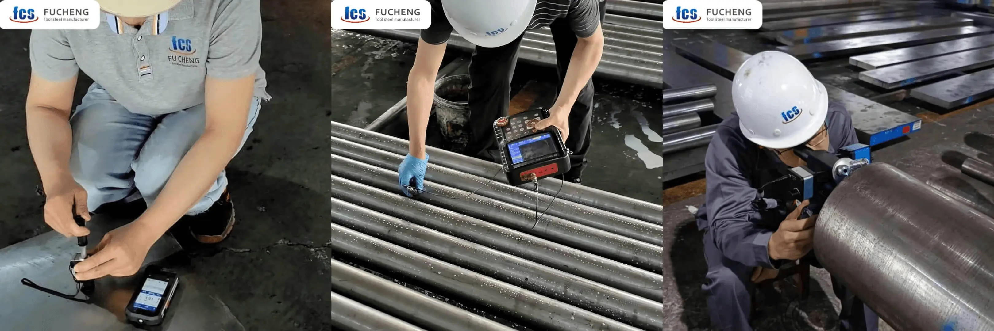
Most mills just random-sample to save time. Honestly, we don’t play that game. We run our Full Control System (FCS) on every single block. Here is our 7-step difference:
- Chemical Check: We test every heat via OES. We never blindly trust raw material certs.
- Dimensions: We rely on precision CMMs, not just micrometers, ensuring perfect H7/g6 fits.
- NDT (UT & MT): Others scan the top surface and call it a day. We physically rotate the steel for multi-angle UT to catch deep voids.
- Hardness: We take multiple surface readings and average them to guarantee uniform heat treatment.
- Carbide Distribution: We strictly enforce a ≤1.5 rating. If the network is poor, it drops out.
- Metallography: Grain size gets a strict double-check—once after forging, and again right before loading the truck.
- Final Compliance: Found a flaw? We cut that section off entirely. We never secretly weld over defects before signing the final MTC.
Conclusion
Tool steel never forgives a shortcut. Your inspection process shouldn’t either. Whether you lean on ASTM or ISO standards, rigorous testing acts as your only safety net against catastrophic die failures. You must verify the chemical makeup, run precise hardness checks, and rely on real NDT methods before any block touches your CNC machine. The best time to catch a fatal defect is right at the receiving dock, not halfway through an expensive production run. Stop risking your tooling budget on unverified metal. Use the benchmarks in this guide to audit your current suppliers immediately. Need a partner who actually guarantees tool steel quality and provides complete inspection reports? Send us your material specs or drawings today, and let’s get your next project started the right way.