
Introduction:
A mold designed to last 500,000 cycles that fails at 50,000 isn’t bad luck — it’s a signal. Something went wrong upstream. Ignoring that signal costs far more than the mold itself.
Premature mold failure disrupts production schedules. It strains supplier relationships. It raises hard questions about material selection, process parameters, and accountability. At FCS Steel, those questions get answered.
This piece breaks down what qualifies as premature failure. You’ll see what causes it, and how FCS Steel’s structured technical response workflow turns a crisis into a traceable, solvable problem — with preventive measures built in so it doesn’t happen again.
What Qualifies as “Early” Mold Failure
The industry has a framework for this — and it matters more than most buyers realize.
|
SPI Mold Class |
Expected Design Life (Minimum) |
Typical Maximum Cycles |
|---|---|---|
|
Class 101 (Hardened Steel Tool) |
1,000,000 cycles |
2–3 million shots (if run correctly) |
|
Class 103 |
Up to 500,000 cycles |
— |
|
Class 104 |
100,000 cycles |
— |
These aren’t aspirational numbers. They’re engineering commitments — built on the assumption the mold runs under proper conditions.
A tool that falls well short of those benchmarks? That’s premature failure. Full stop.
The Numbers That Define “Too Soon”
Practical rule: once a mold hits 60–70% of its rated cycle life, start budgeting for replacement. That’s normal end-of-life planning. Anything before that threshold — under standard processing conditions — is a problem worth investigating.
Real production examples:
-
Class 101 tool showing core cracks or cavity wear at 200,000–400,000 cycles → premature
-
Class 103 tool needing replacement before 200,000 cycles with standard materials → premature
-
Aluminum prototype mold wearing out before 2,000 parts → premature
Early Warning Signals in the Cycle Count:
Defect patterns flag trouble fast. Flash appearing before 20–30% of rated cycles points to damaged sealing surfaces — not process drift. Surface delamination in the first third of tool life means abnormal wear rates, not acceptable aging.
4 Pillars of Premature Mold Failure: A Technical Audit

-
Metallurgical Faults & The “61 HRC” Trap
Pushing tool steel (like H13 or SKD61) to 61 HRC or higher creates a brittle microstructure where fracture toughness ($K_{IC}$) collapses. Beyond hardness, internal “seeds of destruction”—such as non-metallic inclusions, carbide segregation, or coarse grains from overheating—act as subsurface stress risers. Failure to perform triple-tempering leaves residual tensile stress, turning the tool into a “ticking clock.”
-
Electrical Discharge Machining leaves a recast “white layer” saturated with micro-cracks. If this brittle zone isn’t removed via secondary fine-passes, polishing, or stress-relief annealing, it provides a ready-made path for cracks to migrate into the mold core.
-
Design-Induced Stress Concentrations
Fractures rarely occur on flats; they hunt for sharp corners, narrow gaps, and abrupt profile transitions. Improperly placed conformal cooling channels—too close to the cavity—trigger rapid thermal fatigue. These cracks often masquerade as “wear” but are fundamentally design defects.
-
Operational & Thermal Overloading
-
Pressure Imbalance: Excessive injection pressure or uneven clamping force concentrates loads, cracking plates and stressing tie bars.
-
Thermal Gradients: Blocked cooling channels or mineral buildup creates localized hot spots. These gradients drive expansion and distortion, accelerating fatigue at sharp radii that cannot shed heat.
-
Corrosive Erosion: Resins releasing off-gases cause surface pitting. These pits evolve into stress risers, significantly shortening the tool’s lifespan if corrosion-resistant grades (like S136) are ignored.
-
Master’s Tip: Stop treating early failure as “bad luck.” Most issues stem from the 61 HRC threshold or EDM recast layers.
3. FCS Steel’s 4-Pillar Technical Response System for Early Mold Failures
Pillar 1: Material Specification as the First Line of Defense
The response to early mold failure starts before anyone touches a failed tool. It starts with asking whether the right steel was specified in the first place.
FCS Steel’s standard position: for hot-work molds showing premature cracking, thermal fatigue, or heat-checking, the correct specification is H13 / 1.2344 / SKD61 — a chromium-molybdenum-vanadium hot-work tool steel built to handle repeated thermal cycling without fracturing.
The properties that matter here aren’t abstract:
-
Thermal fatigue resistance — the steel resists surface cracking under rapid heat-and-cool cycles
-
Hot strength — it holds hardness and geometry at high temperatures
-
Toughness — it bends under load rather than shattering
-
Hardenability — it responds in a consistent, predictable way to heat treatment, right through the cross-section
That last point is where many early failures begin. A steel that hardens unevenly creates internal stress gradients. Those gradients don’t show up with any warning. They just crack — at the worst possible moment in a production run.
For applications where material cleanliness is critical — complex cavities, polished surfaces, safety-critical components — FCS specifies SKD61-ESR, the electroslag remelted variant. ESR cuts down non-metallic inclusions: the microscopic impurities that act as crack starting points under cyclic load. The result is a more uniform microstructure, a more consistent heat-treatment response, and better fatigue life you can measure.
Pillar 2: Heat Treatment Controls That Stop Failures From Being Built In
A poor heat treatment doesn’t just weaken a mold. It programs it to fail.
FCS Steel’s processing controls address this head-on. Two variables carry the most risk.
-
Heating rate is the first. Rapid heating causes surface oxidation and decarburization — a loss of carbon at the steel’s surface that reduces hardness and speeds up heat-checking and early wear. FCS’s standard protocol requires controlled heating rates, paired with protective atmosphere furnaces or anti-decarburization agents to protect surface integrity through the full thermal cycle.
-
Quench selection is the second. The cooling medium and method must match the actual geometry and cross-section of the workpiece. Get it wrong, and the quench itself introduces cracking or distortion that causes premature failure — a tool damaged not in service, but on the way to it.
Both controls follow the same logic: the failure investigation starts at the process record, not the fractured part.
Pillar 3: Failure Traceability and Root Cause Documentation
A mold that fails before its rated life isn’t just a production setback. FCS Steel’s response workflow treats it as a diagnostic event — not something to absorb and move past.
Every premature failure triggers a structured review that works backward through the production record:
-
Steel certification and incoming inspection data — did the specified grade arrive as ordered, and did it pass dimensional and hardness checks?
-
Heat treatment logs — did the austenitizing temperature, hold time, and quench sequence match the protocol?
-
Machining records — did finish passes and annealing address the EDM white layer?
-
Process parameters from production — injection pressure, clamping force, cycle time, and recorded temperatures
The goal isn’t to assign blame. The goal is to find which upstream decision caused the downstream failure — and put that decision on paper. Without that paper trail, the same failure shows up on the next tool built to the same spec.
Pillar 4: Preventive Specification Updates for Future Tools
The fourth pillar is what stops the problem from coming back.
Once FCS Steel identifies the root cause, the technical response workflow produces a specification update — a concrete change to material grade, heat treatment protocol, design geometry review, or surface treatment requirement. That update applies to any future tool running the same application or material.
This is where the workflow closes the loop. The failure analysis doesn’t sit in a report. It enters the specification. The next mold built for that application carries the lesson from the last one that failed.
That’s the standard. Four pillars. One structured response. No recycled failures.
Step-by-Step Workflow of FCS Steel When a Mold Fails Early
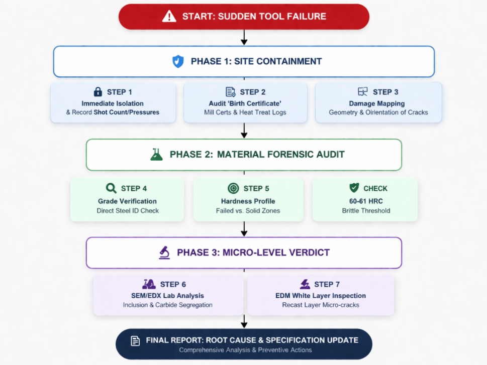
A mold that fails ahead of schedule creates two problems. The tool is damaged. The data is at risk. Process conditions tell the failure story — but that story vanishes fast if no one captures it. At FCS Steel, the response workflow runs on one principle: every early failure has a traceable cause. Finding it requires the right information, collected in the right order.
Here’s how that order runs.
Phase 1: On-Site “Crime Scene” Containment (Steps 1-3)
The moment a mold fails, the clock starts. Step 1 is immediate isolation—no “test shots” allowed. We record the exact shot count, injection pressure, and cycle time. These are the “biological markers” of the failure. Step 2 pulls the “Birth Certificate”: we audit the mill heat numbers, quench records, and surface treatment logs. Step 3 is damage mapping; we don’t just describe a crack—we measure its geometry and orientation relative to sharp corners and cooling channels. This separates operational accidents from deep-seated design flaws.
Phase 2: Material & Hardness Forensic Audit (Steps 4-5)
We move from the tool to the steel itself. Step 4 is a cold-hard verification of steel identity—did a low-grade blank sneak into the CNC line? Step 5 is the hardness audit. We compare the failure zone against undamaged areas. If we see a reading at or above 60–61 HRC, we’ve found our culprit: a brittle microstructure. We also check the tempering history—without three full tempering cycles, the mold is a “ticking clock” of residual stress.
Phase 3: Micro-Failure & EDM Analysis (Steps 6-7)
For complex fractures, we go to the lab. Step 6 uses SEM (Scanning Electron Microscopy) to hunt for non-metallic inclusions or carbide segregation—the microscopic “seeds” of a crack. Step 7 targets the silent killer: the EDM White Layer. This recast zone is essentially untempered martensite, riddled with micro-cracks. If this layer wasn’t removed through secondary polishing or annealing, it acts as a high-speed lane for crack propagation.
5. Preventive Strategies to Avoid Early Mold Failure
Failure investigation is valuable. Prevention is cheaper.
Once FCS Steel’s root cause analysis wraps up on a failed tool, the findings don’t stay in the report. They feed into a set of upstream controls built to stop the same failure from hitting the next build. These aren’t generic maintenance reminders. They’re focused interventions — each one targeting a failure mode that shows up again and again in early-failure case files.
Mold Failure Prevention: Actionable Checklist
|
Phase |
Core Action |
Technical Standard |
|
Material |
Match Grade to Use |
H13/1.2344 (Hot-work); S136H/1.2316 (Corrosive) |
|
Verify |
Audit Certifications |
Verify Mill Certificates, not just labels on blanks |
|
Heat Treat |
Triple Tempering |
Execute 2–3 cycles to ensure toughness band |
|
Hardness |
Set Safety Ceiling |
Reject tools at or above 60–61 HRC (prevents brittleness) |
|
Design |
Radius Optimization |
Remove sharp corners; check Cooling Channel wall thickness |
Conclusion
A mold failing too soon does not mean guaranteed downtime. It shows your upstream process needs a fix. We designed the FCS Steel 4-Pillar Technical Response System for this specific problem. Our team uncovers the root cause fast. This stops one broken mold from shutting down your entire production line.
Dealing with a fractured mold today? Or want to secure your next tooling project? Do not wait for the damage to spread. Contact the FCS Steel technical team today. Bring your failure data. We will build a strategy and get your production back on track.