Have you ever picked the wrong die steel? I’ve seen production costs spiral out of control because of this mistake. Getting 1.2344 (H13) tool steel right isn’t just about checking specification boxes. You need to understand what happens when your tool hits 700°C under load. I recommend looking beyond the basics.
Most buyers focus on hardness numbers. They miss critical factors. ESR purity matters. Tempering cycles matter too. These factors determine whether your die lasts 10,000 cycles or 100,000 cycles. Based on my experience, datasheets won’t tell you everything about material selection. Here’s what you need to know…
Material Selection Criteria and Specifications
For hot work applications, 1.2344 (AISI H13) die steel stands out as the go-to choice. Finding the right material means balancing three main factors: how long it lasts, what it costs, and how well it performs under pressure. This balance matters because your tooling investment needs to deliver consistent results while staying within budget constraints.
Steel Grade Identification and Standards
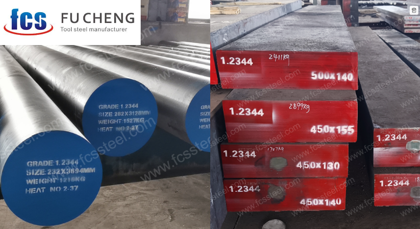
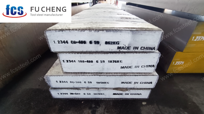
The 1.2344 designation appears under several names across different international standards. You might see it listed as AISI H13 in American specifications, JIS SKD61 tool steel in Japanese standards, or X40CrMoV5-1 tool steel in European contexts. This multi-standard compliance (DIN 1.2344, ASTM A681, BS BH13) makes sourcing easier globally. Die casting operations rely heavily on this grade, along with hot forging shops, extrusion tool makers, and injection molding facilities that need cores capable of handling extreme temperatures.
Chemical Composition Requirements
Silicon and manganese appear in smaller amounts but matter just as much. Silicon (0.80–1.20%) acts as a deoxidizer during steelmaking and boosts toughness. Manganese (0.20–0.50%) helps neutralize sulfur’s harmful effects while supporting hardenability. The phosphorus and sulfur limits (both ≤ 0.030%) prevent brittleness and cracking during hot work cycles. These tight composition controls directly translate to longer die life and fewer catastrophic failures.
Procurement Specifications and Quality Requirements
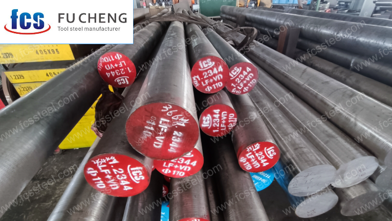
For premium die steel production, manufacturers typically use IM/EAF + LF + VD processes as the foundation. But if you’re working with critical die-casting or forging dies, ESR (Electro-Slag Remelting) becomes essential. ESR refining dramatically improves purity and uniformity while reducing inclusions that can compromise die performance. The isotropy enhancement from ESR matters most in applications where dies face extreme thermal cycling and mechanical stress.
Production standards also demand a minimum forging reduction ratio of 5:1. This ratio isn’t arbitrary—it guarantees the soundness of both billets and finished forgings by eliminating internal voids and ensuring proper material flow throughout the steel structure.
Grain Size and Internal Structure Control
The grain structure determines how your die steel performs under pressure. ASTM E112 standards require a grain size of ≥ 6.0, and finer grains directly translate to better toughness and extended die lifespan. This becomes particularly important in hot work applications where thermal fatigue can destroy poorly structured steel.
Macrostructure control follows ASTM E381 guidelines, targeting maximum class 2A/2B. This specification prevents three critical defects: central porosity, chemical segregation, and star cracks. Validation requires etched cross-section inspection to verify internal soundness. Skip this step, and you risk discovering structural problems only after machining expensive dies.
Dimensional Standards and Surface Quality
Premium die steel demands tight straightness and flatness tolerances. Machined parts need ≤ 1.5 mm/m deviation, while as-supplied forms can accept ≤ 2.5 mm/m. These tolerances matter because distortion during heat treatment can ruin precision dies that took hours to machine.
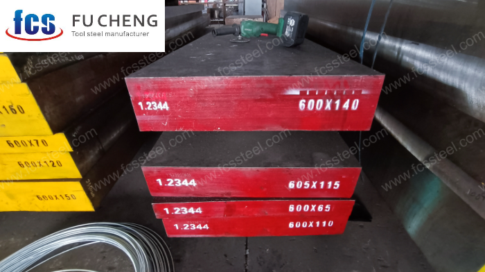
Stock forms come in three standard conditions: annealed (≤ 235 HB) for easy machining, pre-hardened (460–500 BHN) for reduced heat treatment steps, or custom precision-machined blanks ready for final finishing. Surface conditions range from black (as-rolled) through rough machined to precision finished. Regardless of finish level, all parts must pass rigorous inspection for scale, cracks, decarburization, and segregation. Both visual examination and magnetic particle inspection are non-negotiable quality checkpoints.
Mechanical Properties and Testing Standards
Die steel mechanical properties aren’t suggestions—they’re requirements that determine whether your dies survive production runs or fail prematurely. Here’s what quality material delivers:
Property
Specification
Why It Matters
Tensile Strength
1550–2050 MPa
Resists deformation under pressure
Yield Strength
1000–1380 MPa
Prevents permanent die distortion
Impact Toughness
20–40 J/cm²
Withstands thermal shock cycles
Hardness (post-quench)
45–52 HRC
Maintains cutting edge integrity
Hardness (annealed)
≤ 235 HB
Allows efficient machining
Elongation
10–15%
Provides ductility to prevent brittle failure
Modulus of Elasticity
215 GPa
Ensures dimensional stability
Non-Destructive Testing Requirements
Quality verification doesn’t stop at mechanical testing. Every piece of die steel needs 100% ultrasonic (UT) testing to NDT Class 3 standards per SEP specifications. This testing becomes absolutely critical for pressure die casting applications where internal defects can cause catastrophic die failure. UT inspection confirms the absence of internal cracks, porosity, and inclusions that surface inspection might miss.
Surface inspection complements UT testing through magnetic particle or dye penetration methods on bars and plates. These techniques catch surface-breaking defects that could propagate under service loads. Together, these inspection methods provide the confidence that your die steel meets the exacting standards modern die making demands.
Understanding Soft Annealing of 1.2344 (H13) Die Steel
Soft annealing stands as a critical heat treatment process for 1.2344 (AISI H13) die steel. This thermal process transforms the steel’s structure to make it easier to machine while preparing it for subsequent hardening operations. The treatment relieves internal stress, refines carbides, and creates a more uniform microstructure that responds better to final heat treatments.
Why Soft Annealing Matters for Your Die Steel
The benefits of soft annealing extend beyond simple hardness reduction. Machine shops value this process because it cuts down on tool wear during rough machining operations. Drilling, milling, and turning become faster and more economical. The steel also becomes more predictable during final hardening, which means fewer rejected parts and better dimensional stability.
Internal stresses from forging or previous manufacturing steps can cause warping or cracking during later operations. Soft annealing releases these locked-in stresses, giving you a more stable starting point. The process also breaks down carbide networks and chains that form during solidification, redistributing these hard particles into a finer, more uniform pattern throughout the steel matrix.
Temperature and Timing Requirements
The heating temperature for 1.2344 soft annealing typically falls between 760–810°C. This range works well for most applications and provides consistent results. Some specialized workflows push the upper limit to 850°C when specific microstructure modifications are needed, though this remains less common in standard die-making operations.
Soaking time connects directly to part size. A simple rule guides the process: allow 1 to 2 hours for every 25 millimeters of section thickness. Thicker sections need more time for heat to penetrate evenly and complete the transformation throughout the entire cross-section. Rushing this stage leaves core areas under-processed while surface zones over-anneal.
Controlled Cooling Makes the Difference
Cooling rate separates successful soft annealing from failed attempts. The parts must cool inside the furnace at a controlled rate of 10–20°C per hour. This slow cooling continues until the steel temperature drops below 600–650°C. After reaching this threshold, the parts can finish cooling in still air without risk of hardening or stress development.
Fast cooling defeats the purpose of annealing. Rapid temperature drops can re-introduce stress or create unwanted hard structures. The controlled furnace cooling gives carbides time to spheroidize and the matrix time to reach its softest, most machinable state.
Stress Relief Annealing of 1.2344 (H13) Die Steel
Stress relief annealing targets internal stresses that develop in 1.2344 (H13) die steel after machining, forging, or welding operations. The process helps maintain dimensional stability and reduces the chance of problems during subsequent heat treatment. For tool shops working with precision dies and molds, this step can make the difference between a stable workpiece and one that warps during hardening.
Main Process Parameters and Technical Data
The annealing temperature sits between 610–660°C (1130–1220°F). You need a controlled furnace environment to hold this range consistently. The holding time varies with part thickness—a good rule is 2 hours for every 25 mm (1 inch) of the thickest cross-section. Most operations run between 2 and 6 hours total.
Cooling needs to happen slowly inside the furnace. Pull the parts only after they’ve cooled to room temperature. Air cooling defeats the purpose because it can reintroduce the stresses you just removed. If you’re working with critical or high-value tooling, consider annealing under protective gas or in a vacuum. This keeps oxidation and decarburization off the surface.
Application Scenarios and Typical Use Cases
After rough machining: Dies, molds, and large tool components often need stress relief once roughing is complete. The process restores dimensional stability and clears residual stresses before you move to finishing operations. This is standard practice in mold shops that machine large cavities or complex geometries.
Post-welding: Repair welds concentrate stress in localized zones. Stress relief annealing equalizes these areas and helps the part hold its shape through final machining and hardening. Welded die repair work benefits most from this step.
Forging dies and die casting molds: These tools see heavy loads and thermal cycling. Stress relief before hardening prevents warping and cracking. Many manufacturers treat this as a non-negotiable step in their standard operating procedure.
Physical Benefits and Steel Performance
Dimensional Stability: Stress relief cuts down on distortion during quenching and in-service use. Parts hold their shape better through the final heat treatment cycle. Shops report fewer surprises with out-of-flatness or unexpected movement.
Crack and Distortion Prevention: The process equalizes the internal structure and lowers the risk of unexpected cracking. Stress concentrations that might trigger failure during hardening get smoothed out. This is especially valuable for large, expensive tooling where a single crack can scrap the entire piece.
Hardness Control: The soft microstructure after annealing—typically below 240 HB—makes final finishing and precision machining easier. Cutting tools last longer, and surface finishes come out cleaner. Manufacturers see fewer issues with warping or dimensional drift in later heat treatment cycles.
Operational Best Practices
Don’t air cool or water quench after stress relief annealing. You’ll undo everything the process achieved. Keep the parts in the furnace until they reach room temperature. Pulling them early brings back the internal stresses.
Stay below 660°C. Higher temperatures risk grain coarsening or unwanted microstructure changes. The steel might lose some of its beneficial properties, and you’ll end up with a less stable workpiece.
Skip normalization procedures as a substitute for stress relief. Normalization isn’t designed for H13/1.2344 die steel in this context. The cooling rates and thermal cycles don’t match what you need to remove machining or welding stresses effectively.
Hardening Process for Customized 1.2344 (H13) Die Steel
I recommend hardening as a key step for 1.2344 (H13) die steel in hot work applications. This process helps you achieve the target hardness and wear resistance. It lets your components handle tough operating conditions. It keeps them stable. It extends tool life.
Purpose and Expected Hardening Results
Achieve working hardness of 52–56 HRC after quenching, before tempering.
Boost high-temperature wear resistance, red hardness, and impact toughness.
Strengthen the steel’s defense against thermal fatigue, heat-checking, and deformation under mechanical load and thermal cycling.
Core Hardening Process Steps and Critical Parameters
Multi-step Preheating: Stage 1: 500–600°C Stage 2: 730–780°C (you can go up to 816°C if you need better stress reduction) Good preheat cuts cracking risk. It controls heat spread.
Austenitizing: Temperature range: 1010–1080°C (I suggest 1020–1050°C based on section thickness)
Hold time: 30–60 minutes at temperature. Don’t exceed 90 minutes. This prevents grain growth.
Quenching: I recommend air quenching for most shapes. You can use oil quenching for complex dies. Never use water. Water causes severe cracking.
Target cooling rate: At least 30°C/min from austenitizing temp to 530°C. Keep core-surface temperature gap below 100°C in the 400–450°C range.
Post-quench Hardness: Achieve 52–56 HRC before tempering. Machining Allowance: I suggest you add ~0.2% extra allowance before heat treatment. This covers possible distortion or size changes.
Special Metallurgical Notes
Secondary Hardening: Carbide particles (Ti, V, Mo) form during hardening and tempering. This boosts stability against softening.
Service-dependent tempering follows hardening right away. I recommend 2 cycles of 1 hour at 550–650°C. This gives you final hardness between 38–53 HRC.
Tempering 1.2344 (H13) Die Steel: Process Parameters and Best Practices
Tempering stands as the critical heat treatment step that determines whether your 1.2344 (H13) die steel performs as expected or fails prematurely. After years working with hot work tooling, I’ve seen how proper tempering transforms brittle hardened steel into durable, reliable dies. The process balances hardness with toughness while relieving dangerous internal stresses left from quenching. Whether you’re making hot work dies, extrusion tools, or plastic molds, getting this right matters.
Why Tempering Matters for H13 Die Steel
Tempering does three essential things for your tooling. First, it reduces the brittleness that comes from quenching while increasing the material’s ability to absorb impact and resist cracking. Dies see brutal conditions – thermal cycling, mechanical shock, and abrasive wear all at once. Without proper tempering, they simply won’t last.
Second, tempering releases the internal stresses trapped in the steel during rapid quenching. These residual stresses can cause warping during use or even spontaneous cracking. The tempering process lets the steel relax and stabilize its dimensions. Finally, tempering creates the ideal microstructure: tempered martensite with fine alloy carbides distributed throughout. This combination delivers both strength and ductility, exactly what demanding die and tooling applications require.
Temperature Selection and Critical Zones
The standard tempering range for 1.2344 runs from 500°C to 650°C, but most shops work between 530°C and 600°C. There’s a good reason for this narrower window. Between 430°C and 550°C exists what we call the “brittle zone” or temper embrittlement range. Tempering in this zone can produce tools that appear fine but crack unexpectedly under load.
For die casting applications specifically, the sweet spot sits between 538°C and 590°C (1000-1095°F). This range gives you hardness around 43-48 HRC, which handles the thermal shock of molten metal while maintaining edge stability. The final hardness range spans 38-53 HRC depending on your exact application, but hot work dies typically target that 43-48 HRC zone.
Tempering Cycles and Time Requirements
Multiple tempering cycles work better than a single long treatment. Plan for at least two cycles, though three cycles prove better for high-stress tools or critical applications. Each cycle needs a minimum holding time of 2 hours or 5 minutes per millimeter of cross-section, whichever gives you more time. For a die with 25mm thick sections, that means at least 30 minutes per cycle at temperature.
Between cycles, let the part air cool completely to room temperature. This cooling period lets the structure stabilize and ensures uniform stress relief throughout the entire piece. Rushing this step by water quenching or forced air cooling can undo the benefits you’re trying to achieve.
Summary Table: Recommended Tempering Parameters for 1.2344 (H13) Die Steel
Tempering Temp (°C)
Hold Time/Cycle
Cycles
Hardness Range (HRC)
Notes
530
2 h or 5 min/mm
2–3
50–48
Secondary hardening peak
570
2 h or 5 min/mm
2–3
47–44
Hot-work die standard
600
2 h or 5 min/mm
2–3
42–39
Enhances shock resistance
620+
2 h or 5 min/mm
2–3
38–35
Not recommended—rapid hardness loss
Nitriding Process Parameters and Results
Nitriding stands out as a proven surface engineering technique that significantly enhances the performance characteristics of customized 1.2344 (H13) die steel. This thermochemical treatment delivers exceptional improvements in hardness, wear resistance, and thermal fatigue performance—critical factors for demanding industrial applications.
Key Process Variables
Temperature control sits at the heart of effective nitriding. The optimal range falls between 500°C and 540°C, with specific temperatures selected based on your intended application requirements. Treatment duration varies from 10 to 40 hours, and this flexibility allows precise control over case depth development. A shorter cycle of 10-12 hours at 510°C creates a case depth of 0.10-0.13 mm. Extend the process to 25 hours at 520°C, and the case depth reaches approximately 0.25 mm.
Two primary atmosphere options exist for nitriding. Gas nitriding relies on ammonia as the nitrogen source, while plasma (pulsed) nitriding employs a carefully balanced mixture—typically 25% nitrogen and 75% hydrogen at a 70% duty cycle. Each method offers distinct advantages depending on part geometry and desired surface characteristics.
Performance Outcomes
Surface hardness typically reaches 1100 HV, though optimized processing conditions can push this value to 1250 HV. The relationship between treatment duration and surface hardness shows clear patterns: extending the cycle from 6 to 16 hours elevates hardness from 860 HV to over 1100 HV.
Case depth ranges from 0.1 mm for shorter, lower-temperature treatments to 0.5 mm for extended high-temperature cycles. Standard processing at 525°C generally produces a maximum case depth of 0.3 mm. The compound layer thickness responds directly to both temperature and time—at 540°C, this layer can double compared to treatments at 520°C.
Performance, Testing Data, and Industrial Outcomes
Wear and Friction: Nitrided H13 die steel performs better at high temperatures—up to 700°C. It reduces friction and supports oxide (TiO₂, Cr₂O₃) formation after coating wear.
Fatigue and Thermal Crack Resistance: The hard nitrided surface and tough core increase resistance to both fatigue and thermal cracking. I’ve seen this make a real difference in die longevity.
Surface Roughness: Smoothness improves with longer nitriding times. This results in finer die surfaces, which I suggest for demanding tooling tasks.
Tested Data Examples:
Hardness: 860 HV (6h), 1100 HV (16h), up to 1250 HV with optimal ammonia flow.
Layer Thickness: 91.9 µm (single nitriding), 135 µm (double), 180 µm (triple).
Wear Testing: Nitrided samples achieved 235 m sliding at room temperature and 1099 m at 700°C.
Process Control: Nitrogen’s effective diffusion coefficient at 520°C is 1.069 × 10⁻¹² m²/s. Case depth connects directly with the square root of time. This makes results predictable.
Practical Application, Testing, and Recommendations
Preferred Methods: I recommend gas or plasma nitriding for uniform, controlled layers. Choose the method based on part geometry and required uniformity.
Testing: You must test post-process surface hardness (DIN EN ISO 6507-1:2018). Check coating adhesion via Rockwell indentation (ISO 26443:2008).
Case Depth Control: I suggest maintaining 0.2–0.5 mm for durability without brittleness. 0.3 mm at 525°C is a critical upper limit.
EDM Surfaces: Always polish or machine the white layer after nitriding. This prevents crack initiation on electrical discharge machined parts.
Carburizing Process Parameters & Technical Data
Temperature and Case Depth
The carburizing temperature ranges from 870 to 930°C, which matches H13’s alloy content. This range allows controlled carbon diffusion without compromising the steel’s base properties. The typical carburized case depth falls between 0.6 and 1.2 mm. Larger sections—those exceeding 30 mm—require longer cycle times to achieve the same case depth uniformity.
Soak Time and Preoxidation
Reaching a 1 mm hardened case at 900°C takes 6 to 16 hours per cycle. The variation depends on furnace efficiency and component geometry. A preoxidation step at 600°C for 24 hours is common practice. This forms a thin iron oxide layer on the surface, which promotes more uniform and deeper carbon penetration during the carburizing stage.
Quenching Strategy
After carburizing, you need to quench immediately. Oil quenching works best for thick or intricate dies because it delivers better hardness retention. Thin parts can be air-quenched to reduce the risk of cracking. The choice between oil and air depends on part geometry and the required balance between hardness and toughness.
Tempering Cycles
Tempering should be done above 500°C, typically around 550 to 600°C. Running 2 to 3 cycles of 2 hours each reduces brittleness and stabilizes the final hardness. This step is critical for dies that face thermal cycling and mechanical shock during service.
The carburized layer converts to tempered martensite with fine secondary carbides. This microstructure delivers high abrasion resistance while maintaining a strong core. The hardness gradient from surface to core ensures that the die can withstand both surface wear and bulk mechanical stresses. Industry cases show that properly carburized H13 dies can double or even triple their operational life compared to untreated components.
Key Factors Influencing Quality
Steel Chemistry: Chromium and molybdenum levels slow carbon diffusion. You need strict atmosphere and cycle control.
Preoxidation Quality: Uniformity and depth of oxide layer are critical for process success.
Carburizing Regime: Exact temperature and time selection tunes both depth and hardness gradient.
Component Design: Geometry and thickness affect thermal behavior and carbon paths.
Quenching Practice: Proper media and agitation prevent distortion. They ensure uniform surface hardening.
Tempering Rigor: Well-controlled cycles secure final stress relief and secondary hardening response.
Industrial Cautions and Recommendations
Control preoxidation carefully. Follow with immediate sequential carburizing for maximum layer uniformity.
Understand alloy limitations. H13’s high alloy content demands careful process tuning. This avoids patchy or shallow cases.
I recommend you weigh alternatives. For most tool steels in high-cycle service, nitriding or nitrocarburizing gives more predictable results with less risk. But carburizing works best in rare, high-abrasion scenarios. Based on my experience, this is where it truly shines.
Carburizing remains a focused and process-intensive option for extreme-duty H13 die steel tooling. Traditional surface treatments do not work here. Carburizing delivers improved wear performance. It extends tool operational life in the harshest tooling environments.
Surface Engineering: PVD/CVD Coatings
Surface Engineering: PVD/CVD Coatings for 1.2344 (H13) Die Steel Physical Vapor Deposition (PVD) and Chemical Vapor Deposition (CVD) are common surface engineering technologies. They enhance the durability and efficiency of customized 1.2344 (H13) die steel. These coatings work well in die casting and hot-work tool applications. Purpose and Major Effects Key benefits: PVD/CVD coatings provide strong surface wear resistance. They reduce friction. They also increase oxidation and corrosion resistance. This improves die performance and longevity under high mechanical and thermal loads.
Commercial impact: I recommend these advanced coatings for critical components in high-heat, abrasive environments. Examples include die-casting cores, ejector pins, and hot-forging inserts.
Common Coating Materials and Their Properties Popular PVD/CVD coatings: TiN (Titanium Nitride) TiCN (Titanium Carbonitride) CrN (Chromium Nitride) TiAlN (Titanium Aluminum Nitride) Hardness of coatings: >2000 HV—many times harder than the substrate.
PVD/CVD coating hardness: 2000–2400 HV. H13 substrate after tempering: 44–52 HRC or 420–530 HV. Coating thickness: 2–6 µm. This ensures a thin, uniform, and high-performance surface. Friction coefficient: TiN, CrN: 0.4–0.7 (uncoated H13: >0.8). Service temperature stability: TiN, CrN: stable up to 500–700°C TiAlN: up to ~800°C (excellent for aluminum/magnesium die casting).
Process Overview and Technical Notes
Application timing: Apply after final tempering. This prevents damage to the coating from further heat treatments.
Surface preparation: Clean and polish the surface (Ra < 0.2 µm is common). Use microblasting when needed. This ensures optimal coating adhesion.
Enhanced results: Combine PVD/CVD with prior surface hardening (e.g., nitriding). This achieves higher wear life. Nitrided layer: 1000–1200 HV.
PVD advantages: I prefer PVD for components exposed to temperatures below 500°C. It avoids re-tempering the base steel. It preserves dimensional accuracy.
Performance Results, Industrial Data, and Case Studies
Service life: Field tests show PVD TiN or CrN coatings provide 2–5× longer service life for H13 die-casting tools versus uncoated steel. This means less downtime and longer maintenance intervals.
Wear resistance: Up to 80% reduction in adhesive wear. There is also a marked decrease in aluminum soldering (sticking of die materials). This is key for aluminum and zinc die casting.
Example applications: Foundries report coated core pins, ejector pins, and die cavities require less frequent replacement. They need less intervention during production runs.
Quantifiable benefits:
Surface hardness of PVD/CVD-coated H13: 2000–2400 HV
Die maintenance costs drop by 25–50% per part. This results in clear ROI for most tooling operations.
Quick Reference: Key Data and Benefits of PVD/CVD Coatings on H13 Die Steel
Attribute
Value/Range
Benefit/Note
Coatings used
TiN, CrN, TiAlN, TiCN
PVD/CVD
Thickness
2–6 µm
Uniform, thin, no dimensional impact
Coating hardness
>2000 HV
Extreme surface durability
Substrate hardness
44–52 HRC
Required for coating success
Wear life improvement
2–5×
Field and lab-confirmed
Friction coefficient
0.4–0.7
40–60% less vs. uncoated steel
Maintenance cost saving
25–50%
Fast ROI in high-output production
Application scope
Die casting cores/cavities
Ideal for Al/Mg/Zn dies, shot sleeves, etc.
Based on my experience, selecting the optimal PVD/CVD coating and process can boost the performance of your H13 die steel tools. You’ll achieve longer uptime, lower costs, and better quality in high-value hot work operations. I recommend evaluating your specific application conditions. Match them with the right coating type. This will help you get the most value from this technology.
Quality Control Checkpoints for Customized 1.2344 (H13) Die Steel
I believe good quality assurance for customized 1.2344 (H13) die steel starts at raw material selection. It continues through every processing and finishing stage. Each checkpoint uses recognized standards and validated test data. This guarantees both compliance and long-term die performance.
Incoming Material Inspection
Chemical Composition Validation
Confirm all chemical elements are within standard ranges (e.g., DIN 1.2344, AISI H13, ASTM A681).
Typical target: C 0.39–0.43%, Si 0.80–1.20%, Mn 0.20–0.50%, Cr 4.75–5.50%, Mo 1.10–1.75%, V 0.80–1.20%, P & S ≤ 0.030%.
Ultrasonic Testing (UT) for Internal Defects
100% ultrasonic inspection performed per ASTM E381 or SEP 1921-84.
Acceptance threshold: Inclusions or defects >1 mm flagged for rejection.
Grain Size Analysis
Use microscopy to verify fine, even grain size without abnormal growth.
Fine, uniform grains enhance die steel toughness.
Quality Checks After Heat Treatment
Hardness Testing
Use Rockwell C scale (HRC). The standard is HRC 50–52 post-tempering.
Out-of-spec readings (too high/low) may result in batch rejection.
Size and Tolerance Inspection
I recommend you evaluate straightness, flatness, and parallelism to project specs.
Allow ~0.2% machining margin before heat treatment. Check that final shifts stay within 0.2–0.3%.
Microstructure Validation
Perform analysis to confirm a martensite matrix. Look for <2% retained austenite and even carbide spread.
Rate grain size. Check for nonmetallic inclusions post-heat treatment.
Certification
Verify products meet EN 10204/3.1 standards. Document all property benchmarks.
Surface Engineering Inspection and Validation
Surface Hardness and Case Depth
Test nitrided or treated surfaces using Vickers (HV) or microhardness scales.
Typical nitrided surface: 0.1–0.3 mm thick, 950–1150 HV surface hardness.
Case Depth Assessment
Confirm case depth with microsectional analysis for applications that need extended wear.
Coating/Layer Adhesion and Wear Resistance
Carry out scratch and tribology tests. Inspect for absence of decarburization or surface flaws (ISO 9443/7788).
Industrial data: Ion nitriding may give 3–5× greater tool life due to high wear resistance.
Documentation and Traceability
Recordkeeping and Certifications
Based on my experience, you should maintain complete, traceable files for each block or batch. Include heat number, chemical and mechanical test results, size checks, heat treatment cycles, and UT records.
All shipments must include EN 10204/3.1 certification and test summaries.
Quality System Compliance
I suggest you require ISO 9001:2008/2015 accreditation from suppliers. This includes audit schedules and calibrated inspection equipment.
Conclusion
1.2344 (H13) is a widely used hot-work tool steel, but its real performance depends heavily on material purity, steelmaking route, microstructure, heat treatment, machining behavior, and strict quality control. A well-selected supplier should provide consistent mechanical properties, accurate dimensional tolerances, reliable heat treatment, and full documentation.
By following the technical and procurement criteria outlined in this guide, engineers and buyers can significantly reduce tooling failures, increase operational stability, and extend tool life in demanding hot-work applications.