Introduction:
Your production line stops cold. A critical mold just cracked. You are only months into a five-year life plan. The financial hit comes fast. Deadlines fall apart. The blame game starts.
Mold failure creates a crisis of trust. You need answers, not guesses. Was it the steel grade? Bad heat treatment? At FCS Steel, we don’t believe in “bad luck.” We look at the hard evidence. This guide shows you our response system. We find the real root cause. Then, we apply fixes that get you back online and keep you running.
Defining Early Mold Failure and Root Causes
Industry standards like the SPI mold classifications set clear benchmarks for tool life. They range from Class 101 (≥1 million cycles) down to Class 105 prototypes. Material selection sets the baseline. You might choose aluminum for short runs or hardened steel for high volume. However, we call failure “premature” if a tool breaks before it reaches 60–70% of its expected design life. Watch for warning signs. Flash or surface delamination in the first 20–30% of production signals trouble.
What Drives Premature Breakdown
Premature failure seldom comes from just one issue. It often happens because six technical factors come together:
- Material Quality: You need steel with the right toughness. Using blocks with internal defects (like inclusions or segregation) hurts structural integrity right away.
- Processing Errors: Watch out for poor heat treatment, like overheating or weak tempering. You must also remove brittle EDM “white layers.” If you don’t, the steel surface stays micro-cracked and weak.
- Design Flaws: Bad geometry concentrates stress. Sharp internal corners or cooling channels placed too close to cavity surfaces will speed up fatigue failure.
- Thermal Management: Uneven cooling creates thermal gradients. This leads to distortion and heat checking (thermal fatigue) in high-stress zones.
- Process Mismatches: Too much injection pressure or wrong clamping force creates physical overload. This pushes thin sections and parting lines past their yield strength.
- Surface Degradation: Corrosion from aggressive resins, contamination, or abrasive wear does damage. It destroys precision sealing faces and forces you to retire the tool.
FCS Steel’s 4-Pillar System
FCS Steel uses a structured framework to prevent mold failures. We address problems through four core technical areas. Each pillar tackles specific failure modes. You get measurable controls and documented standards. The system covers material specs, processing rules, quality checks, and ongoing support.
Pillar 1: Material Specification Based on Heat Load
Steel grade selection is the primary defense against mold breakdown. FCS Steel maps alloy properties directly to heat-load requirements to prevent premature failure.
- H13 / 1.2344 / SKD61 steel: This Cr–Mo–V hot-work alloy is the industry standard for high-temperature injection. Its unique chemistry resists thermal fatigue and maintains structural integrity during aggressive heating-cooling cycles.
- Thermal Fatigue vs. Wear Resistance: While 1.2379 (D2) steel offers superior wear resistance at room temperature, it lacks the toughness required for hot mold service. For tools prone to heat checking or thermal shock cracking, shifting from 1.2379 to 1.2344 (SKD61) is essential.
- The ESR Advantage: For safety-critical tools or mirror-finish surfaces, we utilize SKD61-ESR (Electroslag Remelting). This process eliminates non-metallic inclusions, ensuring a cleaner microstructure.
- Result: Uniform heat-treatment response, no localized weak spots, and significantly higher fatigue resistance in high-stress zones.
Pillar 2: Processing Controls That Stop Heat-Treatment Damage
- Controlled heating protocols stop decarburization and oxidation defects. We require gradual heating rates. Fast temperature rise removes surface carbon. Decarburization cuts surface hardness. The weak surface layer develops heat checking too soon. Wear damage appears faster.
- Protective atmosphere heating is standard for critical tooling. Controlled-atmosphere furnaces block oxygen contact. Some setups use charcoal or anti-decarburization agents packed around the workpiece. Both methods keep surface carbon intact. They stop oxidation scale from forming.
- Quenching strategy matches part shape to cooling medium. Small tools with simple shapes can take faster oil quenches. Large blocks with internal features need slower polymer quenches. Or controlled-rate gas quenching. The cooling method controls three failure risks: low hardness from slow cooling, warping from uneven cooling rates, and quench cracking from extreme heat differences.
- Molds that cracked during heat treatment before? We adjust quench media. We reduce cooling rate at critical temps. We add stress-relief steps before final hardening. These changes fix the root cause. No more remaking the same weak tool.
Pillar 3: Non-Destructive Testing and Toughness Validation
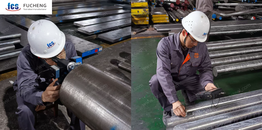
You cannot see internal steel defects with the naked eye. That is why FCS Steel mandates process validation before any block leaves our floor. We don’t just rely on mill certificates; we verify the physical reality of the metal.
- Every high-performance block undergoes Ultrasonic Testing (UT). We adhere to strict standards like SEP 1921 Class E/e or ASTM A388. This scan finds internal voids, cracks, or heavy segregation that act as initiation points for future failure. If a block fails the UT scan, it gets scrapped. It never reaches your machine shop.
- We also prioritize transverse impact toughness. Hardness tells you how well a steel resists wear, but toughness tells you how well it resists cracking. For critical molds, we conduct random sampling impact tests (Charpy V-notch). This ensures the microstructure affects toughness in all directions, not just with the grain. This step is the “insurance policy” against catastrophic snapping under load.
Pillar 4: Lifecycle Technical Stewardship
Our job does not end when the steel is delivered. Pillar 4 covers the operational life of your mold. We operate as technical partners, not just material vendors.
- We provide welding and repair guidelines appropriate for the specific alloy. Molds eventually need engineering changes or repair. Using the wrong welding rod or skipping pre-heating can induce stress cracks immediately. We supply exact welding procedures to keep the metallurgical structure intact during repairs.
- We offer active failure analysis support. If a tool struggles, we deploy the diagnostic workflow described below. We help you determine if the issue is the steel, the coating, or the molding parameters. By solving small issues—like early stage heat-checking—we help you extend the tool’s total service life significantly.
Step-by-Step Workflow of FCS Steel
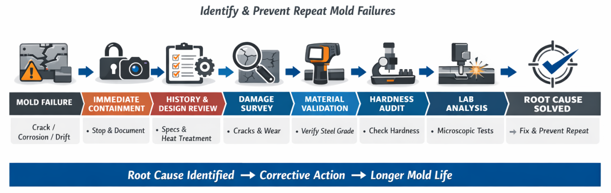
Production stops. Your mold shows cracks, corrosion, or the dimensions drift suddenly. FCS Steel activates a seven-step diagnostic protocol. We combine immediate containment, data collection, and lab-grade failure analysis. Each step builds evidence to find root causes and stop repeat failures.
Step 1: Immediate Containment
Stop and Tag: Halt production immediately. Isolate the mold to prevent unauthorized “quick fixes” that destroy evidence.
Capture Process Data: Record the exact “moment of failure” settings: cavity pressures, temperatures (melt/mold), clamp tonnage, and cycle time.
Preserve Evidence: Photograph the damage before cleaning. Do not polish or weld the cracked area yet.
Step 2: History & Design Review
Verify Specs: Compare your Steel Mill Certificate against the design requirement (e.g., confirming H13 vs. D2).
Audit Heat Treatment: Retrieve the furnace charts. Check for: Austenitizing temperature, quench medium/speed, and number of tempering cycles (minimum 2–3 required).
Map Stress Zones: Identify if the failure occurred at a known stress concentrator (sharp corner, thin wall, or parting line).
Step 3: Damage Survey
Crack Analysis: Measure length and depth. Note if cracks run perpendicular to the machining direction or stress load.
Surface Check: Look for specific patterns:
Heat Checking: Net-like fine cracks (thermal fatigue).
Pitting: Roughness near cooling channels (corrosion).
Galling: Scratches on sliding surfaces (lubrication failure or hardness mismatch).
Step 4: Material Validation
Rule Out Mix-ups: 15–20% of failures are simple grade substitutions. Check the block stamping.
Chemical Test: If in doubt, use a handheld XRF analyzer to confirm alloy content (e.g., ensuring stainless grades have >12% Cr).
Step 5: Hardness Audit
Measure Multiple Points: Test the failed area, the core, and a neutral corner.
Interpret Readings:
Too Hard (>54-60 HRC for H13): Likely under-tempered (brittle).
Soft Spots: Uneven quenching or decarburization.
Variance (>3 HRC gap): Thermal inconsistency in the block.
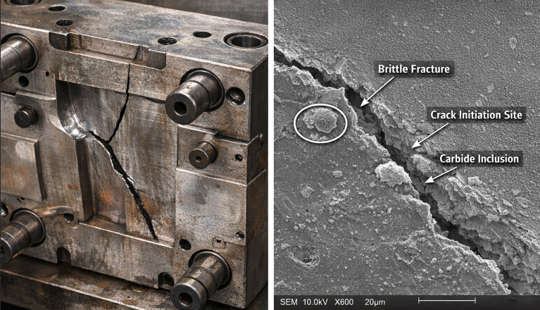
Step 6: Lab Analysis (For Critical Failures)
If the cause remains hidden, use SEM/EDX analysis to find microscopic culprits:
Inclusions: Non-metallic impurities acting as crack starters.
Carbide Networks: Brittle grain boundaries from poor heat treatment.
Fracture Mode: Identify if the break was ductile (overload) or brittle (material flaw).
Step 7: EDM White Layer Check
The Silent Killer: EDM leaves a hard, brittle “white layer” (re-cast layer).
Action: Check if this layer was removed. If cracks originate here, the root cause is skipping the stress-relief or polishing stage after EDM.
FCS Diagnostics in Action
Case 1: The “Wrong Steel” Crisis (Automotive)
Problem: An automotive lens manufacturer faced catastrophic cracking on a mold after just 25,000 shots. Production stalled instantly.
Diagnosis: Our Step 4 Validation revealed the tool was made from D2 (1.2379). The client chose it for wear resistance, but D2 cannot withstand constant heating and cooling. It failed due to thermal shock.
FCS Response: We guided the switch to H13 (1.2344) with proper heat treatment. The replacement tool has since surpassed 150,000 cycles with zero heat checking, proving that toughness—not just hardness—was the missing link.
Case 2: The “Silent” EDM Failure (medical)
Problem: A medical connector molder saw thin core pins snapping repeatedly during ejection. They blamed “bad steel quality.”
Diagnosis: Our lab analysis (Step 6) showed the steel was pure. However, SEM imaging found a microscopic, brittle EDM white layer on the pin surface. The shop had skipped the post-machining stress relief.
FCS Response: We helped implement a mandatory post-EDM stress relief and polishing protocol. Pin breakage dropped to near zero, saving the project timeline.
Conclusion:
Premature mold failure isn’t bad luck. It is a technical problem you can solve. Stop treating breakdowns as just another business cost. Find the root cause immediately. It might be the wrong steel grade. Or perhaps a heat treatment shortcut. Fix the source, and you regain control over your production timeline.
FCS Steel removes the problem entirely. We don’t just patch the crack. Don’t wait for the next shutdown. Contact our technical team today for a failure analysis. We help you swtich from reactive repairs to proactive prevention. This secures the tool life your investment demands.